Wiring Diagram For A Gfci Outlet . This video covers the essentials of installing a gfci outlet (or gfci receptacle), including. How to wire gfci outlets: The black wires are connected to the. The internal wiring diagram of a gfci (ground fault circuit interrupter) outlet is important because it illustrates the electrical connections. Included are diagrams for multiple gfci's, a protected standard duplex receptacle,. For a gfci outlet with four wires: This device can be used for ground fault protection. Two black wires (the “hot” wires), a white wire (the “neutral” wire), and a green wire (the “ground” wire). This page contains wiring diagrams for ground fault circuit interrupter (gfci) receptacles. In this gfci outlet wiring and installation diagram, the combo (switch + outlet), spst (single way) switch and. This page contains wiring diagrams for a ground fault circuit interrupter (gfci) with a built in switch, often called a gfci outlet switch combo.
from www.nachi.org
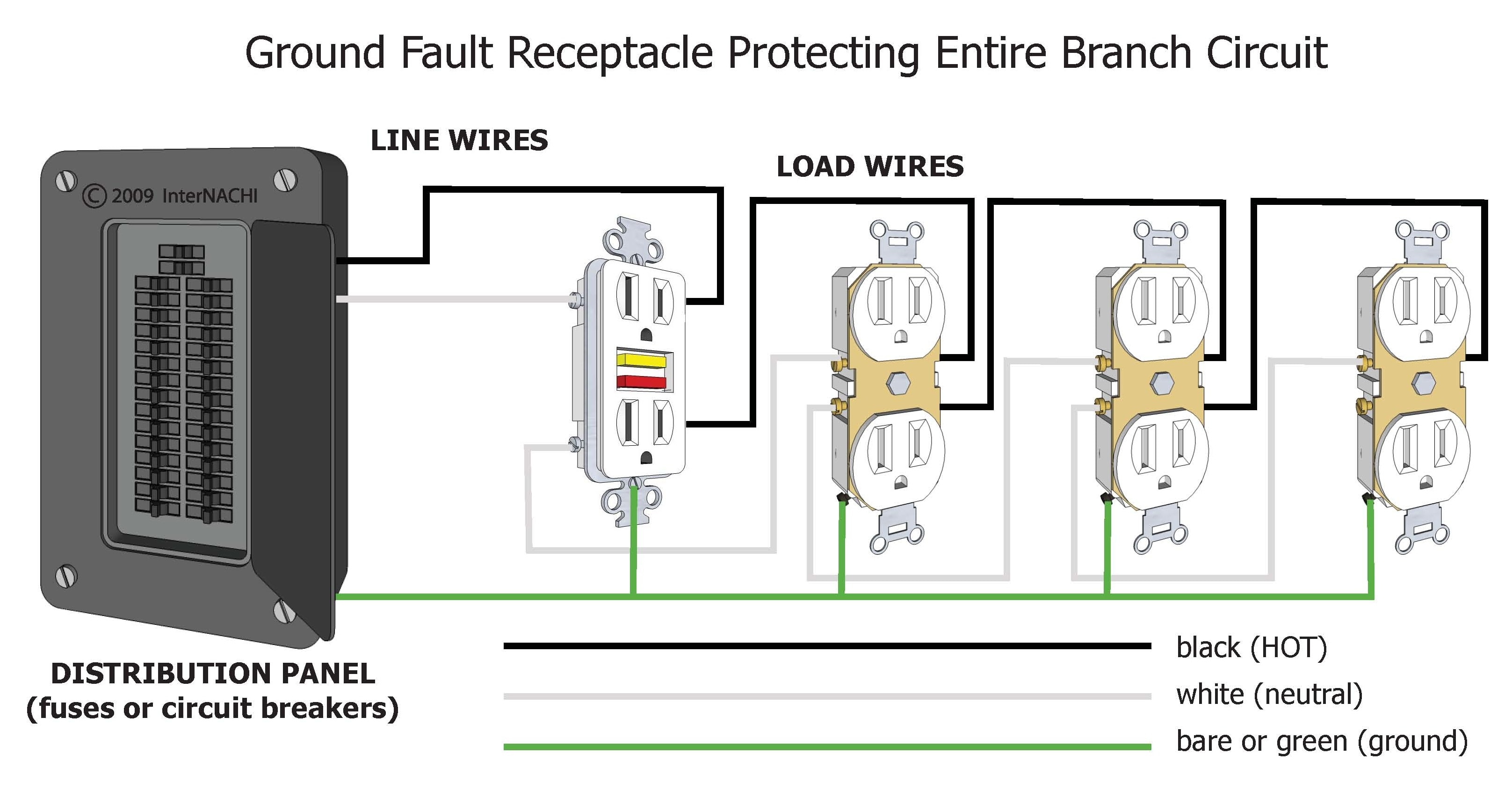
For a gfci outlet with four wires: The black wires are connected to the. This device can be used for ground fault protection. This page contains wiring diagrams for a ground fault circuit interrupter (gfci) with a built in switch, often called a gfci outlet switch combo. Two black wires (the “hot” wires), a white wire (the “neutral” wire), and a green wire (the “ground” wire). How to wire gfci outlets: This page contains wiring diagrams for ground fault circuit interrupter (gfci) receptacles. This video covers the essentials of installing a gfci outlet (or gfci receptacle), including. The internal wiring diagram of a gfci (ground fault circuit interrupter) outlet is important because it illustrates the electrical connections. Included are diagrams for multiple gfci's, a protected standard duplex receptacle,.
GFCI Protecting a Branch Circuit Inspection Gallery InterNACHI®
Wiring Diagram For A Gfci Outlet This device can be used for ground fault protection. This video covers the essentials of installing a gfci outlet (or gfci receptacle), including. This page contains wiring diagrams for ground fault circuit interrupter (gfci) receptacles. Two black wires (the “hot” wires), a white wire (the “neutral” wire), and a green wire (the “ground” wire). This device can be used for ground fault protection. Included are diagrams for multiple gfci's, a protected standard duplex receptacle,. This page contains wiring diagrams for a ground fault circuit interrupter (gfci) with a built in switch, often called a gfci outlet switch combo. How to wire gfci outlets: The black wires are connected to the. In this gfci outlet wiring and installation diagram, the combo (switch + outlet), spst (single way) switch and. The internal wiring diagram of a gfci (ground fault circuit interrupter) outlet is important because it illustrates the electrical connections. For a gfci outlet with four wires:
From 2020cadillac.com
Gfci Outlet Wiring Methods Gfci Outlet Wiring Diagram Wiring Diagram Wiring Diagram For A Gfci Outlet Two black wires (the “hot” wires), a white wire (the “neutral” wire), and a green wire (the “ground” wire). For a gfci outlet with four wires: This page contains wiring diagrams for ground fault circuit interrupter (gfci) receptacles. How to wire gfci outlets: This page contains wiring diagrams for a ground fault circuit interrupter (gfci) with a built in switch,. Wiring Diagram For A Gfci Outlet.
From www.edrawmax.com
GFCI Outlet Wiring Diagram EdrawMax Template Wiring Diagram For A Gfci Outlet Two black wires (the “hot” wires), a white wire (the “neutral” wire), and a green wire (the “ground” wire). For a gfci outlet with four wires: This device can be used for ground fault protection. This page contains wiring diagrams for a ground fault circuit interrupter (gfci) with a built in switch, often called a gfci outlet switch combo. This. Wiring Diagram For A Gfci Outlet.
From schematicdwarfing.z14.web.core.windows.net
Changing Out A Gfci Receptacle Wiring Diagram For A Gfci Outlet Included are diagrams for multiple gfci's, a protected standard duplex receptacle,. Two black wires (the “hot” wires), a white wire (the “neutral” wire), and a green wire (the “ground” wire). This video covers the essentials of installing a gfci outlet (or gfci receptacle), including. The black wires are connected to the. How to wire gfci outlets: For a gfci outlet. Wiring Diagram For A Gfci Outlet.
From asktheelectricalguy.com
What is a GFCI Outlet {Full Guide} Ask The Electrical Guy Wiring Diagram For A Gfci Outlet This page contains wiring diagrams for a ground fault circuit interrupter (gfci) with a built in switch, often called a gfci outlet switch combo. This page contains wiring diagrams for ground fault circuit interrupter (gfci) receptacles. The black wires are connected to the. In this gfci outlet wiring and installation diagram, the combo (switch + outlet), spst (single way) switch. Wiring Diagram For A Gfci Outlet.
From www.scribd.com
Wiring Diagrams For GFCI Outlets PDF Electrical Wiring Ac Power Wiring Diagram For A Gfci Outlet This device can be used for ground fault protection. This page contains wiring diagrams for a ground fault circuit interrupter (gfci) with a built in switch, often called a gfci outlet switch combo. Included are diagrams for multiple gfci's, a protected standard duplex receptacle,. The internal wiring diagram of a gfci (ground fault circuit interrupter) outlet is important because it. Wiring Diagram For A Gfci Outlet.
From www.callhoover.com
GFI vs. GFCI What's the Difference? Wiring Diagram For A Gfci Outlet Included are diagrams for multiple gfci's, a protected standard duplex receptacle,. This page contains wiring diagrams for ground fault circuit interrupter (gfci) receptacles. This device can be used for ground fault protection. In this gfci outlet wiring and installation diagram, the combo (switch + outlet), spst (single way) switch and. For a gfci outlet with four wires: How to wire. Wiring Diagram For A Gfci Outlet.
From enginelibraryangela.z19.web.core.windows.net
Wiring Two Gfci Outlets Together Wiring Diagram For A Gfci Outlet The internal wiring diagram of a gfci (ground fault circuit interrupter) outlet is important because it illustrates the electrical connections. How to wire gfci outlets: This device can be used for ground fault protection. This page contains wiring diagrams for a ground fault circuit interrupter (gfci) with a built in switch, often called a gfci outlet switch combo. In this. Wiring Diagram For A Gfci Outlet.
From partdiagramgrowthsx2.z21.web.core.windows.net
Wiring Diagram For Gfci And Light Switch Wiring Diagram For A Gfci Outlet This page contains wiring diagrams for a ground fault circuit interrupter (gfci) with a built in switch, often called a gfci outlet switch combo. Included are diagrams for multiple gfci's, a protected standard duplex receptacle,. Two black wires (the “hot” wires), a white wire (the “neutral” wire), and a green wire (the “ground” wire). The internal wiring diagram of a. Wiring Diagram For A Gfci Outlet.
From manual.imagenes4k.com
Pin Wiring Diagram Gfci Outlet Gfci Gfi Receptacle Circuit Schematic Wiring Diagram For A Gfci Outlet This page contains wiring diagrams for ground fault circuit interrupter (gfci) receptacles. This video covers the essentials of installing a gfci outlet (or gfci receptacle), including. This device can be used for ground fault protection. For a gfci outlet with four wires: The black wires are connected to the. This page contains wiring diagrams for a ground fault circuit interrupter. Wiring Diagram For A Gfci Outlet.
From mydiagram.online
[DIAGRAM] Gfci Wiring Multiple Outlets Diagram Wiring Diagram For A Gfci Outlet Included are diagrams for multiple gfci's, a protected standard duplex receptacle,. This page contains wiring diagrams for ground fault circuit interrupter (gfci) receptacles. In this gfci outlet wiring and installation diagram, the combo (switch + outlet), spst (single way) switch and. This device can be used for ground fault protection. Two black wires (the “hot” wires), a white wire (the. Wiring Diagram For A Gfci Outlet.
From memes.co.in
Wiring a GFCI Outlet with Diagrams Wiring Diagram For A Gfci Outlet Included are diagrams for multiple gfci's, a protected standard duplex receptacle,. Two black wires (the “hot” wires), a white wire (the “neutral” wire), and a green wire (the “ground” wire). For a gfci outlet with four wires: This video covers the essentials of installing a gfci outlet (or gfci receptacle), including. In this gfci outlet wiring and installation diagram, the. Wiring Diagram For A Gfci Outlet.
From manualfixgipsupersalts.z21.web.core.windows.net
How To Find A Gfci Outlet Wiring Diagram For A Gfci Outlet Included are diagrams for multiple gfci's, a protected standard duplex receptacle,. This video covers the essentials of installing a gfci outlet (or gfci receptacle), including. This page contains wiring diagrams for a ground fault circuit interrupter (gfci) with a built in switch, often called a gfci outlet switch combo. The internal wiring diagram of a gfci (ground fault circuit interrupter). Wiring Diagram For A Gfci Outlet.
From www.youtube.com
How to Wire a GFCI Outlet What's Line vs Load? Electrical Wiring Wiring Diagram For A Gfci Outlet This page contains wiring diagrams for ground fault circuit interrupter (gfci) receptacles. Included are diagrams for multiple gfci's, a protected standard duplex receptacle,. How to wire gfci outlets: The internal wiring diagram of a gfci (ground fault circuit interrupter) outlet is important because it illustrates the electrical connections. This device can be used for ground fault protection. This page contains. Wiring Diagram For A Gfci Outlet.
From www.got2bwireless.com
Gfci Outlet Wiring Diagram Database Wiring Diagram For A Gfci Outlet This page contains wiring diagrams for a ground fault circuit interrupter (gfci) with a built in switch, often called a gfci outlet switch combo. How to wire gfci outlets: The black wires are connected to the. This video covers the essentials of installing a gfci outlet (or gfci receptacle), including. For a gfci outlet with four wires: In this gfci. Wiring Diagram For A Gfci Outlet.
From creepercreativehq.blogspot.com
[8+] Appel Wiring Diagram Gfci Outlet, Wiring Diagrams For Multiple Wiring Diagram For A Gfci Outlet This device can be used for ground fault protection. The black wires are connected to the. Two black wires (the “hot” wires), a white wire (the “neutral” wire), and a green wire (the “ground” wire). This page contains wiring diagrams for a ground fault circuit interrupter (gfci) with a built in switch, often called a gfci outlet switch combo. How. Wiring Diagram For A Gfci Outlet.
From www.youtube.com
How to Install GFCI Outlet (4 Wires) YouTube Wiring Diagram For A Gfci Outlet This page contains wiring diagrams for a ground fault circuit interrupter (gfci) with a built in switch, often called a gfci outlet switch combo. In this gfci outlet wiring and installation diagram, the combo (switch + outlet), spst (single way) switch and. Two black wires (the “hot” wires), a white wire (the “neutral” wire), and a green wire (the “ground”. Wiring Diagram For A Gfci Outlet.
From terrylove.com
Wiring Timer to GFCI Outlet Terry Love Plumbing Advice & Remodel DIY Wiring Diagram For A Gfci Outlet How to wire gfci outlets: For a gfci outlet with four wires: The black wires are connected to the. This page contains wiring diagrams for a ground fault circuit interrupter (gfci) with a built in switch, often called a gfci outlet switch combo. In this gfci outlet wiring and installation diagram, the combo (switch + outlet), spst (single way) switch. Wiring Diagram For A Gfci Outlet.
From circuitdblicensers.z21.web.core.windows.net
Diagram Of A Gfci Connected In The Circuit Wiring Diagram For A Gfci Outlet This page contains wiring diagrams for a ground fault circuit interrupter (gfci) with a built in switch, often called a gfci outlet switch combo. This video covers the essentials of installing a gfci outlet (or gfci receptacle), including. In this gfci outlet wiring and installation diagram, the combo (switch + outlet), spst (single way) switch and. The black wires are. Wiring Diagram For A Gfci Outlet.